Rack And Pinion Linear Motion Calculation

Electric linear actuators linear slides.
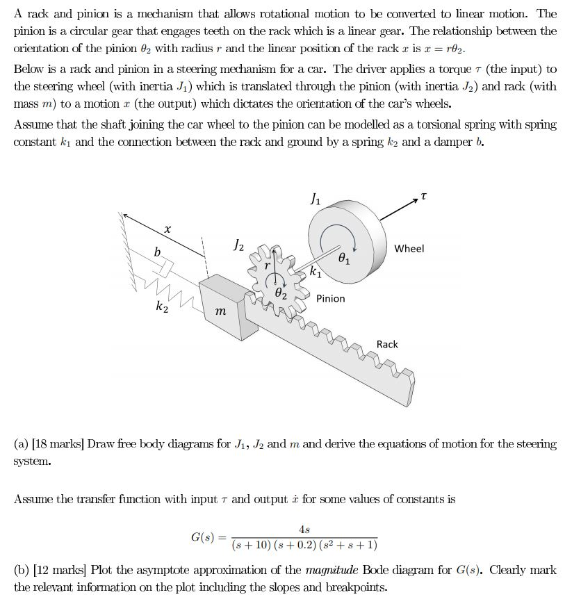
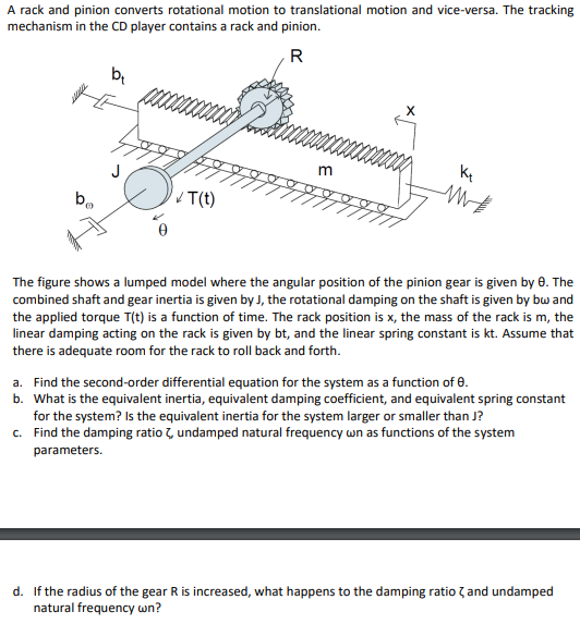
Rack and pinion linear motion calculation. Gear rack and pinion creation of linear motion. Along with the type of drive mechanism you must also determine the dimensions mass and friction coefficient etc. A rack and pinion is a type of linear actuator that comprises a pair of gears which convert rotational motion into linear motion. This pinion engages a linear gear the rack to convert rotational motion into translational motion.
A 20lbs load is fixed on the top of a rack that is driven by two spur gears the pinion is a 28 tooth with a pitch diameter 0 875 driven by a stepping motor m 2218 2 4s holding torque 0 64n m the gear to move the rack assembly is a 64 tooth with a pitch diameter 2 0. That are required for the load calculation. The most common form of this is the use of a pinion attached to a motor that then rests on a gear rack and travels back and forth depending on the direction of the motor shaft rotation. A rack and pinion are used when converting rotational movement to linear motion or vice versa.
A circular gear called the pinion engages teeth on a linear gear bar called the rack. Linear load distribution factor l kh. Moment of inertia calculation for an object in linear motion. Rack and pinion drive calculation and selection.
Calculate rack and pinion. Many gearing applications require converting rotary motion into linear motion. A servomotor directly drives the pinion to either cause the servomotor pinion assembly and attached loads to travel along the rack or less commonly to cause the rack and attached loads to advance and retract. From linear deviation to hardness and straightness all tolerances can be found.
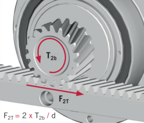
In linear motion applications. And the effects of preload in addition to basic thrust force and drive torque calculations rack and pinion drive sizing is primarily based on three factors. The force the rack sees referred to as the feed force or tangential force. Another advantage for using circular pitch instead of module in these.
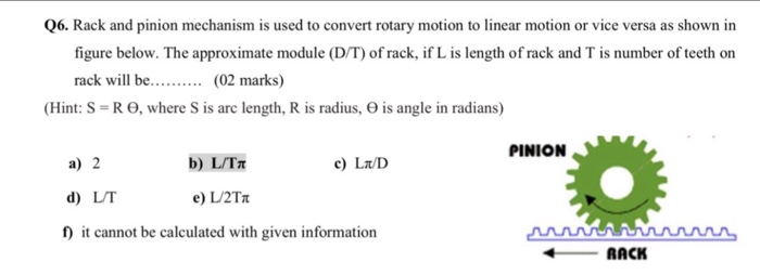
Zd 2 dimensions in mm 1 2012 rack and pinion drive calculation and selection the values given in the load table are based upon uniform smooth operation k h. For some applications the motor is fixed and the rack is the object that is moving. A bar shaped gear with an infinite flat surface radius of a cylindrical gear is called a rack and a meshed spur gear is called a pinion. The tolerances especially with helical teeth are very important.
For a silent and low backlash drive with a long service life it is recommended to use a pinion and rack from 1 supplier.


